RoverCNC LT Build Log - Step 1 - Base Platform
The base platform forms the basic structure of your CNC to build upon thus a rigid and sturdy framework is required. The extrusion chosen for base platform is a 4080 design called the U-Rail. The “U” is primarily the contour of the profile that looks like the letter U, as depicted in the following image.

Before starting the assembly effort you need to make sure what size platform is required of your build, in our case we have chosen the 1.5m x 1.0m platform. The assembly of the base platform requires a few steps that we will try and provide guidance on:
- Attaching the 1616 Ballscrews to the Base Legs
- Measuring the precise Y-Axis length, and cutting the extrusion to length
- Mounting the extrusion base frame to the Legs
— Attaching the 1616 Ballscrews —
The 1616 ballscrew kit includes the actual ballscrew preloaded with the ballnut, the fixed and floating (FK12/FF12) end blocks and the ballnut support block. The components of the ballscrew kit are shown in the image that follows:

In addition to the ballscrew kit, you will also require the FK12/FF12 Sopport Rings and the RoverCNC Legs. First you will need to dress the ballscrew kit into an assembly as shown in the images that follow:


We then need to mount the ballscrews to each end of the legs across the Y-Axis length. The Legs already have been pre-drilled with the appropriate holes to insert the ballscrew assembly into. Using the FK12/FF12 Rings you can support the ballscrew at each end with the legs. This process has to be repeated for each side of the Y-Axis to end up with 2 sets each having 2 legs attached at the end of the ballscrew as shown in the images below:


Once the ballscrew has been attached to each end with the Legs, you should be ready to measure and cut the extrusion to the precise length desired (the extrusion need to be slightly over the length of the desired platform in order to be able to cut it the “right” measured length).
— Measuring and Cutting the Extrusion —
You now need to measure and cut the extrusion length for the Y-Axis reach. You will need to a precise measuring tape and measure the length from and to the inside of the reach of the legs on the upper part where the pre-drilled holes are located, as shown:


Before measuring you need to make sure that the legs are sitting square to get a precise reading. Its not a bad idea to slightly cut it oversize and start shaving it down from there. To cut the extrusions, a Mitre Saw can be used with a carbide blade or a Non-Ferrous Cutting Blade and a squirt of WD40 to keep the heat down. When using a Mitre Saw, you will need to make sure that the saw blade is perfectly square to the table in order to get a good 90 degree cut. It also a good idea to cut both side with a single cut keeping the lengths the same. Both pieces need to be exactly the same lengths! Those having access to a milling machine can run the ends on a milling machine to make them square and keeping the lengths perfectly square.
We now have 2 precise lengths of extrusion that need to be tapped. Using a M5*0.8 Tap, each side of the extrusion holes need to be tapped. There should be 6 holes on each side, and with 2 pieces of extrusion there are a total of 24 holes that need to be tapped. Please tap at least 20-25mm deep in order allow the M5 screws to penetrate enough.

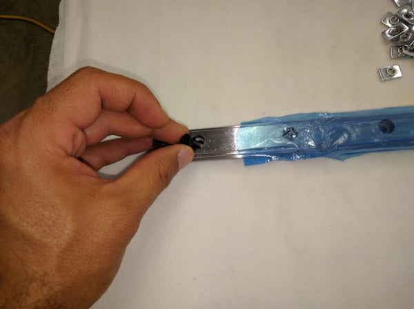
We are now ready to mount the 20mm Linear Block Rails 1.5m length (or your choice of rail length) on to the extrusion. The Gantry Plates are machined to use the 3rd slot from the top (or 2nd slot from the bottom) on the extrusion slot. Before we can slide the rail, we need to insert M5*16 Socket Head Cap Screws into each of the rail’s mounting hole with a M5 T-Nut to the other end of the screw. AT this point we need to go ahead and add some T-Nuts to the inside slot of the extrusion to prepare for the cast iron corner brackets for the cross-beams. This will allow us to slide the rails into the extrusion slot with ease. Once the rails are in place, tighten the first and the last screw to hold the rail in-place.

If the 20mm Linear Block Rails don’t come pre-loaded than you will need to load the linear block onto the rails at this time.


We can now attach the extrusion to the leg assembly.


We need to make sure that everything squares up, if not than we need to figure out where the problems lie. In most cases this would be a problem with the extrusion during the cutting process, the blade may have not been square. You can either fix this by shaving the ends again or by using thin metal shims to square it!


We can now start preparing the 2-4pc extrusion cross-beams (20x40mm). We have used 1.0m lengths but you can use the desired length that you would like your X-Axis travel to be. We can insert the cross-beams into the unused T-Nuts on the Legs that allow us to slip the cross-beam into the adjacent U-Rail 40mm slot. This image shows the unused T-Nuts applied to the legs. The cross-beam needs to slide through the T-Nuts and sit inside the slot as shown:


You can apply the desired amount of cross-beams to complete the base platform.


You need to once more check all the corners for squareness and correct any misalignment.